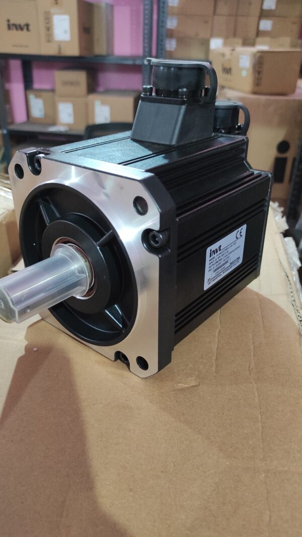
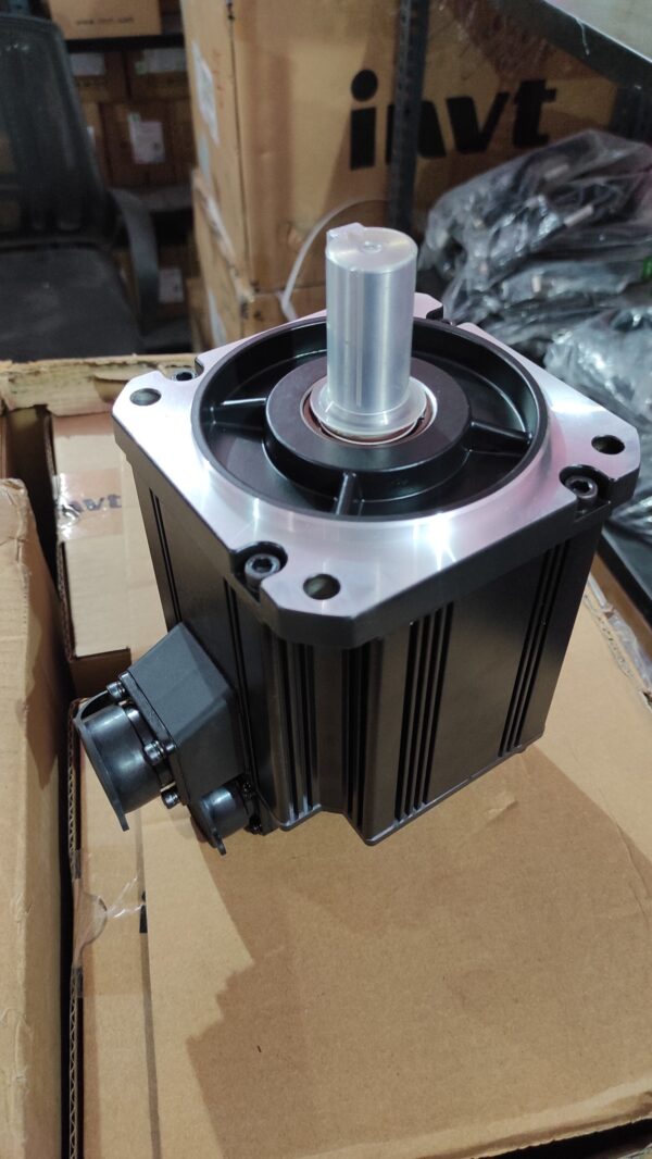
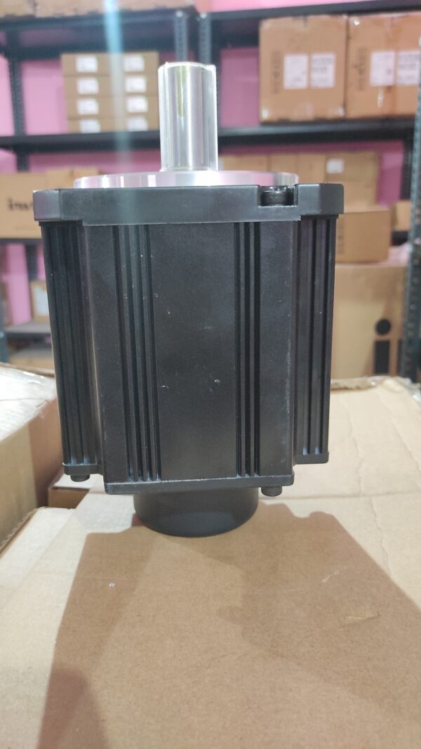
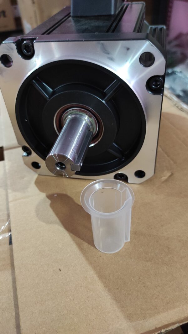
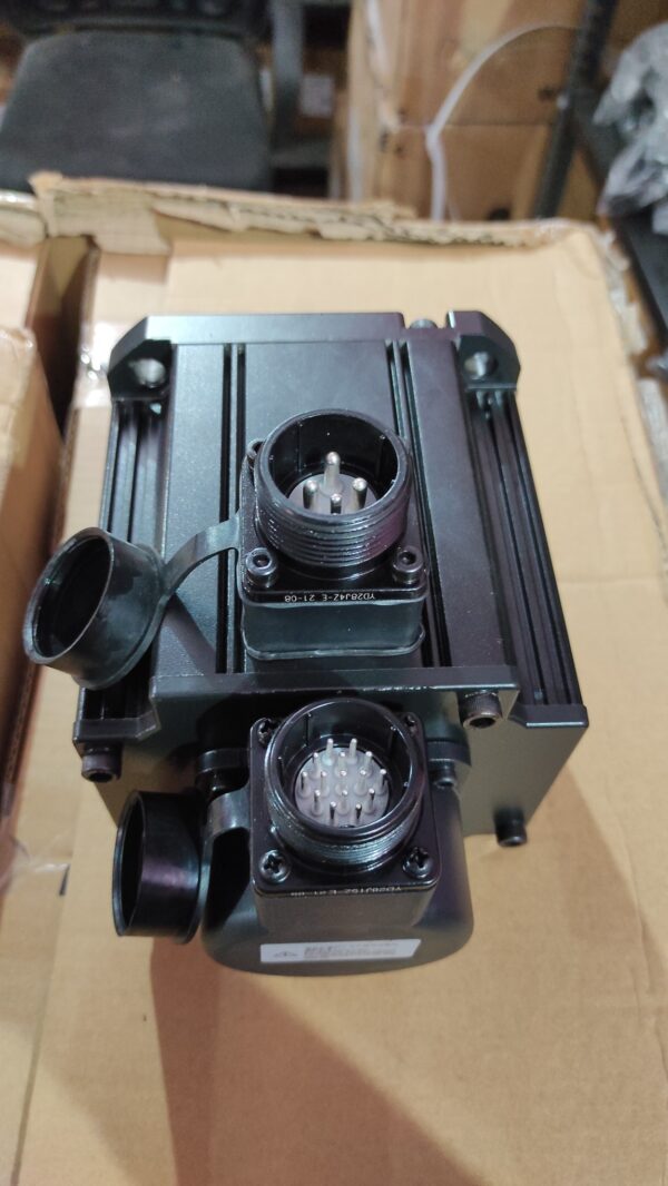
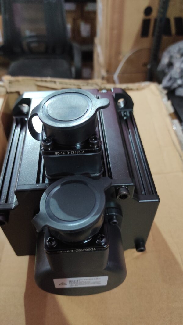
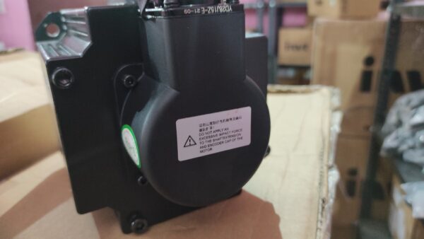
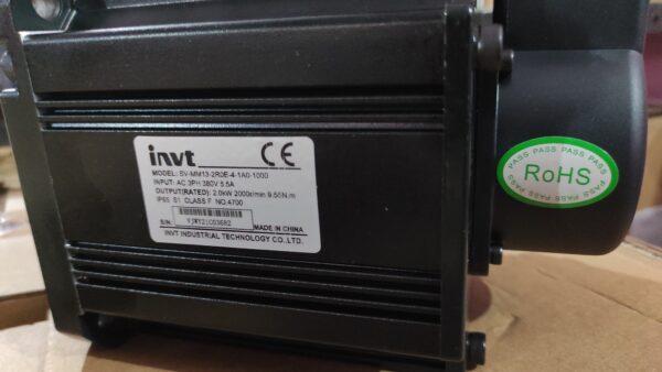
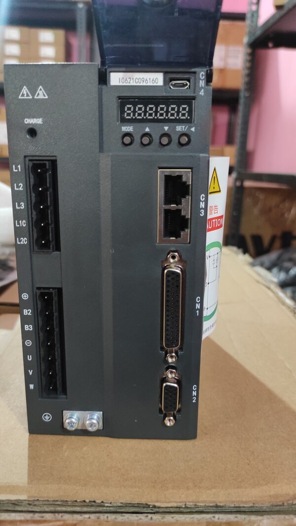
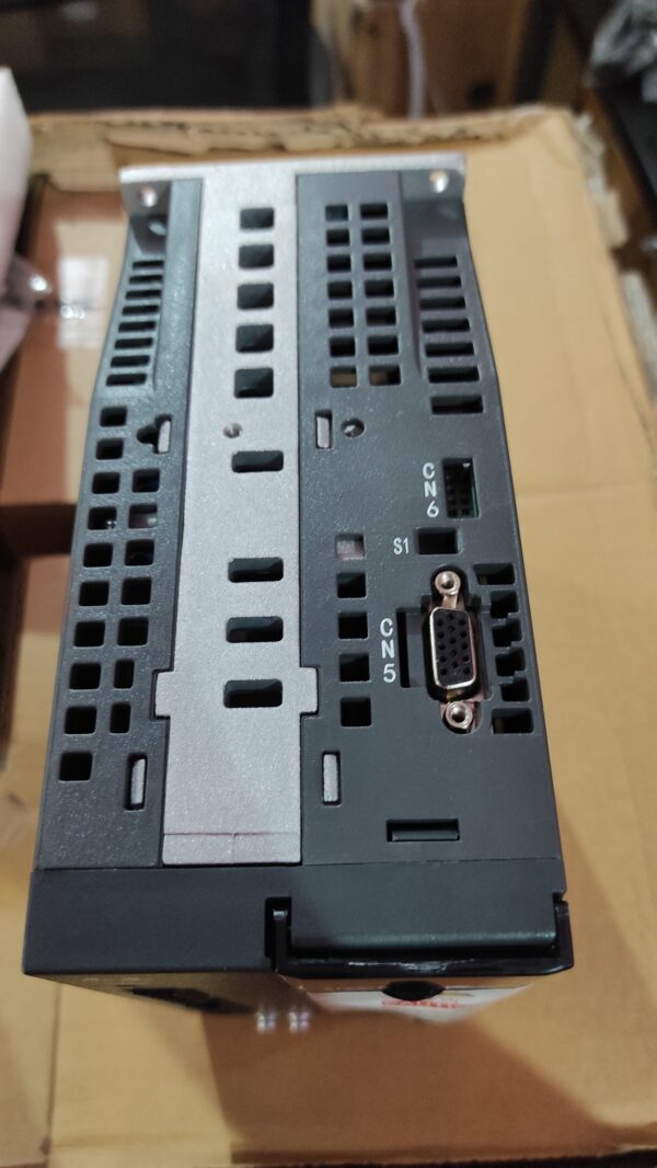
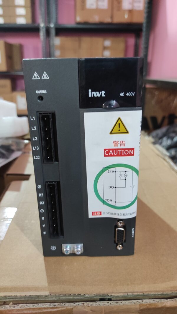
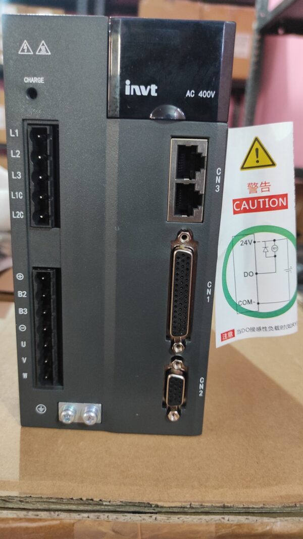
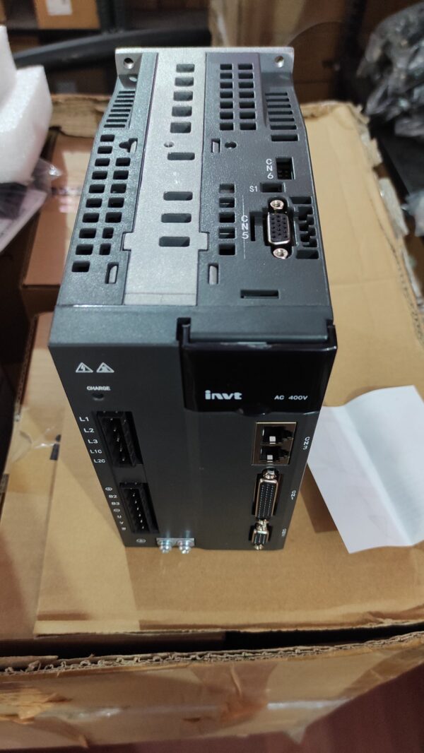
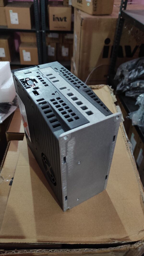
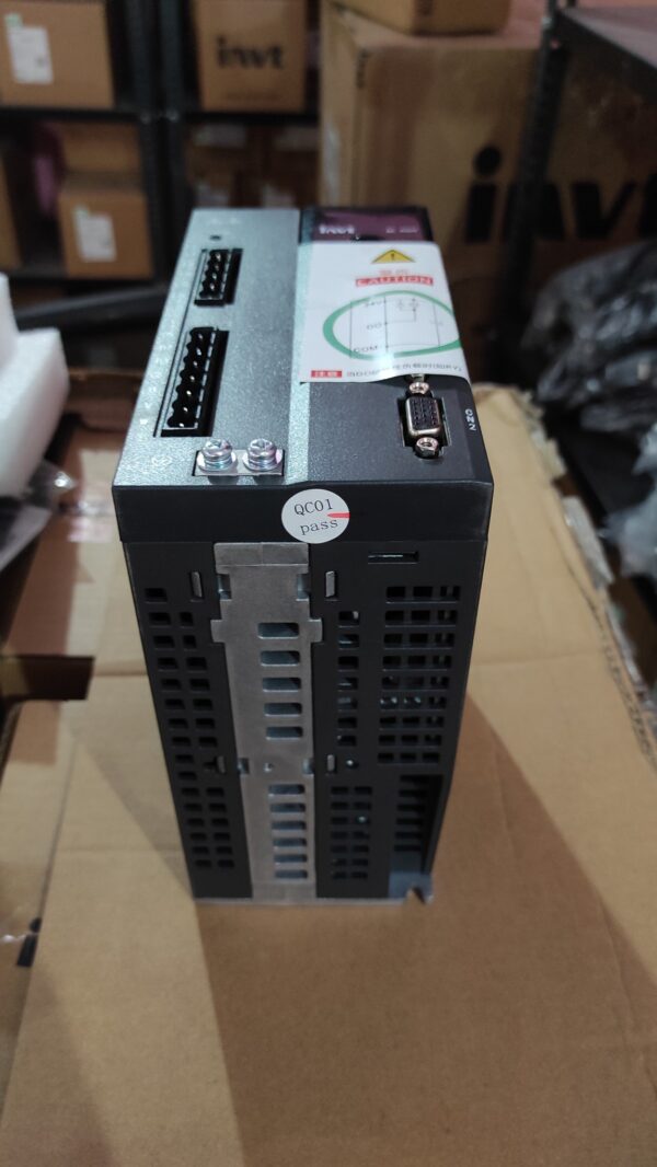
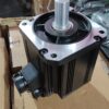
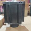
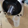
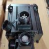
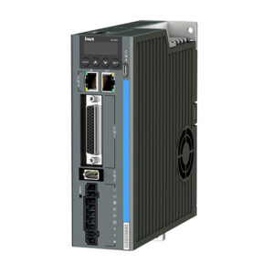
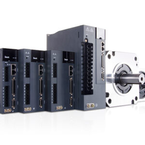
| DA200 Invt Servo Motor (100W–55kW) | |||
| Specification | Description | ||
|
Power supply |
220V system input voltage | 1P/3P AC220V(-15%)–240V(+10%) 47Hz–63Hz | |
| 400V system input voltage | 3P AC380V(-15%)–440V(+10%) 47Hz–63Hz | ||
|
Interface |
Control signal |
Input |
10 inputs for standard type, pulse type and CANopen bus type; 7 inputs for EtherCAT bus type; 5 inputs for MotionNet bus type (the function can be
configured by relevant parameters) |
|
Output |
6 single-end outputs for standard type, pulse type and CANopen bus type; 4 differential outputs for EtherCAT bus type; 1 single-end output for MotionNet bus type (the function can be configured
by related parameters) |
||
|
Analog value |
Input |
3 inputs for standard type (one 16-bit, two 12-bit analog inputs), 2 inputs for others (two 12-bit analog inputs) | |
| Output | 2 outputs (analog output) | ||
|
Pulse signal |
Input |
1 group (mode: open collector input or differential
input) |
|
|
Output |
1 group (differential outputs (A+, A-;B+, B-;Z+, Z-) or open collector outputs (A;B;Z)) | ||
|
2nd encoder |
Input |
Incremental encoder interface (2nd encoder or linear encoder) | |
|
Communication |
USB | 1:1 communication upper PC software (standard) | |
| RS485 | 1:n communication (standard) | ||
| CANopen | 1:n communication (optional) | ||
| Profibus-DP | 1:n communication (optional) | ||
| EtherCAT | 1:n communication (optional | ||
|
Safety terminals |
STO |
Safe torque off (conform to the latest European safety standards) (optional) | |
|
Control mode |
1 Position control; 2 Speed control; 3 Torque
control; 4 Position/Speed mode switching; 5 Speed/Torque mode switching; 6 Position/Torque mode switching; 7 Fully-closed loop control; 8 CANopen mode; 9 EtherCAT mode; 10 MotionNet mode |
||
| DA200 series Invt Servo Motor (100W–55kW) | ||||
| Specification | Description | |||
|
Function |
Position control |
Control input |
1. Retention pulse clearing;
2. Command pulse input disabled; 3. Electronic gear ratio switching; 4. Vibration control switching, etc |
|
| Control output | Positioning completion output, etc | |||
|
Pulse input |
Max. pulse
input frequency |
Optical coupling: differential input 4Mpps, open collector input 200kpps; |
||
|
Pulse input mode |
1. Pulse + direction;
2. CW+CCW; 3. Quadrature |
|||
| Electric gear |
1/10000–1000 times |
|||
|
Filter |
1. Command smoothing filter;
2. FIR filter |
|||
|
Analog input |
Torque limit command
input |
Can independently perform clockwise/ counterclockwise torque limit |
||
|
Vibration control |
Control 5–200Hz forward and whole machine
vibration |
|||
|
Pulse output |
1. Can perform arbitrary frequency division settings under the encoder resolution;
2. B phase reverse function |
|||
|
Speed control |
Control input |
1. Internal command speed 1;
2. Internal command speed 2; 3. Internal command speed 3; 4. Zero speed clamp, etc |
||
| Control output | Speed reaching, etc | |||
|
Analog input |
Speed command
input |
Can be speed command input after relevant setting based on analog
voltage DC±10V |
||
| Torque limit
input |
Can independently arrange clockwise/
counterclockwise torque limit |
|||
| Internal speed
commands |
8 step speed can be switched according to the
external control input |
|||
| ACC/DEC
adjustment of speed command |
ACC/DEC time setting and S curve setting |
|||
| DA200 series Invt Servo Motor (100W–55kW) | ||||
| Specification | Description | |||
| Zero speed clamp | In the speed mode, it can set the operation mode as the speed mode and position mode | |||
| Speed command
filter |
A delay filter of analog input speed command |
|||
| Speed command zero drift control | Zero drift control against outside interference with 0.3mV precision | |||
|
Torque control |
Control input | Zero speed clamp input, etc | ||
| Control output | Speed reaching, etc | |||
|
Analog input |
Torque
command input |
Analog torque command input, gain
and polarity can be set based on analog voltage with 4.88mV precision |
||
| Speed limit
input |
Analog speed limit |
|||
| Speed limit | Set the speed limit by parameters | |||
| Torque command
filter |
A delay filter of the analog input torque command |
|||
| Torque command
zero drift control |
Zero drift control against the outside interference
with 4.88mV precision |
|||
|
Internal position plan |
Plan bits |
128 bits internal position planning, the positioning
can be controlled through communication |
||
|
Route setting |
1. Position; 2. Speed; 3. ACC time; 4. DEC time;
5. Stop timer; 6. Various state output; 7. Operational mode |
|||
|
Homing |
1. LS signal; 2. Z phase signal; 3. LS signal+Z
phase signal; 4. Torque limit signal |
|||
|
Protection |
Hardware protection |
Overvoltage, undervoltage, overcurrent, overspeed, overload, braking resistor overload,
drive overheat, encoder fault and so on |
||
|
Software protection |
Storage fault, initialization fault, I/O distribution abnormalities, and large position deviation | |||
|
Protection and fault record |
1. Record up to 10 faults
2. Can record the key parameters when a fault occurs |
|||
|
Environment |
Operation temperature | 0–45℃ | ||
| Storage temperature | -20–80℃(no frozen) | |||
| Operation/storage humidity | Operation/storage: ≤90%RH (no condensation) | |||
| IP degree | IP20 | |||
| Elevation | Below 1000m altitude | |||
|
Vibration |
≤5.88m/s2, 10–60Hz(Working at the resonance point is not allowed) | |||

There are no reviews yet.